Installing a home EV charger is not just a matter of hanging a box on the wall and plugging it in. The real work happens in the wiring, breaker sizing, and circuit planning that sit behind the plastic cover, and getting those details right is what keeps your car charging reliably and your home electrical system safe. Speaking as an electrician, I look at every charger as a continuous load that has to be matched carefully to the panel, the wire, and the code rules that govern how much current you can safely pull for hours at a time.
How EV charging levels translate into electrical load
When I size an EV circuit, I start by matching the charging level to the home’s electrical capacity, because the jump from a basic Level 1 cord to a full-power Level 2 unit can be the difference between a simple outlet and a panel upgrade. Level 1 charging typically uses a standard 120‑volt receptacle and draws around 12 to 16 amperes, which most modern homes can support without major changes, although it is slow for larger battery packs. Level 2 charging steps up to 240 volts and can range from about 16 amperes to 80 amperes, which is where wire size, breaker rating, and panel space become critical to avoid overloading the system during long charging sessions that qualify as continuous loads under electrical code rules.
Manufacturers usually publish the maximum current draw for each charger model, and that number is the starting point for every design decision that follows. A wall unit rated for 40 amperes at 240 volts, for example, will deliver roughly 9.6 kilowatts of power, while a 48‑ampere unit can push closer to 11.5 kilowatts, which significantly shortens charge times but also places more stress on the home’s service. Many late‑model EVs, such as the Tesla Model 3 or Ford Mustang Mach‑E, can accept these higher Level 2 rates, so owners are tempted to install the biggest charger they can find, yet the smarter move is to match the charger’s output to what the panel and feeder can safely support, a point that is reinforced in technical guidance on EV charging infrastructure.
Why continuous load rules shape breaker and wire sizing
EV chargers are treated as continuous loads because they can run at or near full output for three hours or more, and that classification drives the 125 percent sizing rule that electricians use for both breakers and conductors. If a charger is designed to draw 40 amperes continuously, I do not install it on a 40‑ampere breaker; I multiply the load by 1.25 and land on a 50‑ampere breaker, then choose wire that is rated for at least that 50‑ampere value under the appropriate temperature column. This margin is not a luxury, it is a safety buffer that keeps breakers from nuisance tripping and conductors from running hotter than their insulation is designed to handle during long overnight charging sessions, which is consistent with the continuous load treatment described in home charging guidance.
The same 125 percent rule applies when I am looking at the overall panel load, because the main breaker and service conductors must be able to support the EV circuit on top of existing appliances without exceeding their ratings. A 200‑ampere service can usually absorb a 40‑ or 50‑ampere EV circuit once I run a proper load calculation, but a 100‑ampere service feeding electric heat, a range, and a dryer may not have enough headroom for a high‑power charger. In those cases, I either downsize the charger’s current setting, install a unit that supports load sharing, or recommend a service upgrade, options that align with the practical limits highlighted in residential charging guides that stress panel capacity as a gating factor.
Typical breaker sizes for common EV charger ratings
Once I know the charger’s maximum current, I translate that into a breaker size that respects the continuous load multiplier and the standard breaker ratings available off the shelf. A charger that draws 16 amperes at 240 volts is treated as a 20‑ampere continuous load, so I land it on a 20‑ampere double‑pole breaker with wire sized accordingly, which is a common setup for compact plug‑in hybrids. A 32‑ampere wall unit, which is popular for many battery‑electric models, is treated as a 40‑ampere continuous load and therefore goes on a 40‑ampere breaker, a pairing that matches the example configurations described in technical EV charging references that map current draw to circuit ratings.
Higher output chargers follow the same pattern, they just climb the breaker ladder. A 40‑ampere charger is considered a 50‑ampere continuous load, so I use a 50‑ampere breaker, while a 48‑ampere charger is treated as a 60‑ampere load and requires a 60‑ampere breaker, which is the upper end of what most residential panels can comfortably support for a single branch circuit. Some commercial‑grade units can draw 80 amperes or more, which would push the breaker to 100 amperes, but those are rarely appropriate for typical homes without substantial service upgrades, a limitation echoed in infrastructure reviews that distinguish between residential and commercial charging power levels.
Matching wire gauge to EV circuit amperage
After the breaker is set, I size the wire to handle that breaker rating using the ampacity tables, not the charger’s nameplate current, because the conductor must be able to carry whatever the breaker will allow before it trips. For most residential EV circuits using copper conductors, that means 12 AWG for a 20‑ampere breaker, 10 AWG for 30 amperes, 8 AWG for 40 amperes, and 6 AWG for 60 amperes, assuming typical insulation and installation conditions. These pairings line up with the ampacity guidance embedded in EV charging handbooks that stress the importance of matching conductor size to overcurrent protection rather than to the perceived “average” load.
Voltage drop is the next factor I consider, especially when the charger is located at the far end of a long driveway or detached garage, because long runs of smaller wire can waste energy and reduce charging performance. If the circuit length pushes the voltage drop beyond about 3 percent at full load, I will often step up one wire size, for example moving from 8 AWG to 6 AWG on a 40‑ampere circuit, to keep the voltage at the charger within a healthy range. That approach mirrors the best practices described in residential charging design documents, which highlight conductor upsizing as a straightforward way to control voltage drop on longer EV branch circuits.
Choosing between 120‑volt and 240‑volt circuits
The decision between a 120‑volt Level 1 circuit and a 240‑volt Level 2 circuit is ultimately a tradeoff between charging speed and electrical impact, and I walk homeowners through that balance before pulling any wire. A 120‑volt, 15‑ or 20‑ampere circuit can add roughly 3 to 5 miles of range per hour for many EVs, which may be enough for drivers with short daily commutes and overnight parking, and it often uses existing outlets if they are on dedicated circuits in good condition. In contrast, a 240‑volt Level 2 circuit can add 20 to 40 miles of range per hour depending on the charger and vehicle, which is a dramatic improvement but requires a dedicated double‑pole breaker and appropriately sized conductors, a distinction that is underscored in federal EV charging overviews that compare Level 1 and Level 2 performance.
From an electrical standpoint, 240‑volt circuits are usually more efficient for the same power level because they draw less current for a given kilowatt output, which reduces losses and allows smaller conductors compared with a hypothetical 120‑volt circuit delivering the same power. However, the practical reality is that most homes are already wired with multiple 120‑volt branch circuits and far fewer spare spaces for new 240‑volt breakers, so panel capacity and layout often drive the choice. Guidance on home charging installation notes that many owners start with Level 1 and later upgrade to Level 2 once they understand their driving patterns and have assessed their panel’s ability to support a higher power circuit.
Dedicated circuits, receptacles, and hardwired units
I always treat an EV charger as a dedicated load that deserves its own branch circuit, because sharing with other outlets or appliances invites nuisance trips and potential overheating when everything runs at once. A dedicated circuit means the breaker, conductors, and receptacle or hardwired connection serve only the charger, with no general‑purpose outlets or lighting tied in, which simplifies load calculations and aligns with the dedicated circuit recommendations in installation guides for EV supply equipment. This approach also makes troubleshooting easier, since any trip on that breaker points directly to the charger or its wiring rather than to a mix of household loads.
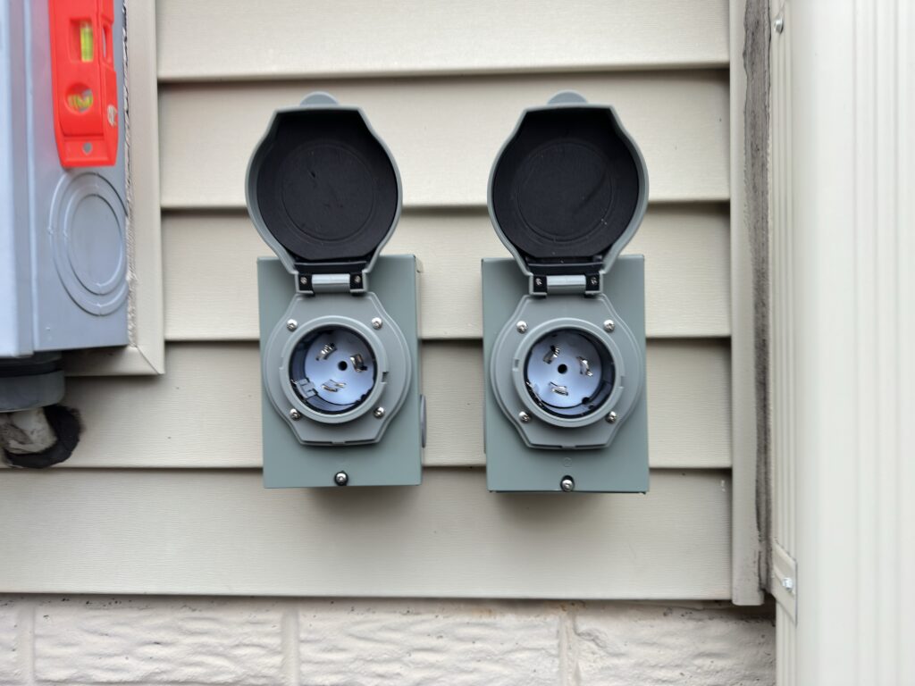
The choice between a plug‑in charger and a hardwired unit usually comes down to flexibility versus robustness. Plug‑in units that use NEMA 14‑50 or 6‑50 receptacles are convenient and can be moved or replaced without opening the panel, but the receptacle and plug blades become additional points of heat and wear that must be installed and maintained carefully. Hardwired chargers eliminate that extra connection, which can improve reliability for high‑amperage units, and many manufacturers specify hardwiring for their 48‑ampere and larger models, a preference that is reflected in field studies of residential charging that document the prevalence of dedicated, hardwired installations for long‑term use.
Panel capacity, load calculations, and service upgrades
Before I commit to any breaker size, I run a load calculation on the main panel to see how much spare capacity is truly available once existing appliances and general lighting are accounted for. The calculation considers fixed loads like electric ranges, dryers, water heaters, and HVAC equipment, then applies demand factors to estimate the realistic maximum draw, which I compare to the main breaker rating and service conductor size. If the numbers show that adding a 50‑ampere EV circuit would push the service beyond its safe limit, I either scale back the charger’s current setting or discuss a service upgrade, an approach that mirrors the panel assessment steps outlined in residential EVSE planning documents.
Service upgrades are not always necessary, but when they are, they can be an opportunity to future‑proof the home for additional EVs or other electric appliances. Moving from a 100‑ampere to a 200‑ampere service, for example, can open enough headroom for two Level 2 chargers, an electric range, and a heat pump, which aligns with the broader electrification trends described in grid integration studies that anticipate higher residential electric loads as transportation and heating shift away from fossil fuels. In some cases, I also look at load management solutions that allow the EV charger to throttle back when the home’s total draw approaches a set limit, which can avoid or defer a full service upgrade while still supporting practical daily charging.
Indoor vs outdoor installations and wiring methods
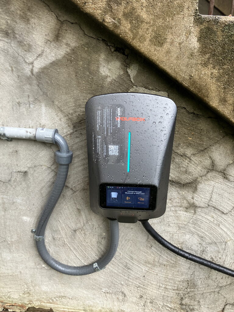
The physical location of the charger dictates how I route and protect the wiring, because indoor garage installations and outdoor driveway setups face very different environmental conditions. For indoor locations on finished walls, I often run cable inside the wall cavity or in surface‑mounted raceway, keeping bends gentle and avoiding exposure to mechanical damage, while unfinished garages may allow for neatly stapled cable runs along studs. Outdoor installations typically require conduit, weather‑rated junction boxes, and fittings that keep moisture out, a set of practices that aligns with the outdoor EVSE installation details in technical installation references that emphasize enclosure ratings and wiring protection.
Weather exposure also affects the choice of charger enclosure and receptacle type, since not every unit is listed for outdoor use and not every outlet cover can protect a plug that remains inserted for months at a time. When I install a plug‑in charger outdoors, I use in‑use covers and weather‑resistant receptacles that are rated for continuous connection, and I pay close attention to drip loops and sealing where the conduit enters the building. These details may seem minor, but they are crucial for long‑term reliability and safety, and they echo the environmental considerations highlighted in outdoor charging guidance that documents how moisture and temperature swings can affect EVSE performance.
Grounding, bonding, and GFCI protection
Proper grounding and bonding are non‑negotiable on EV circuits, because any fault current must have a low‑impedance path back to the source so breakers or ground‑fault devices can clear the fault quickly. I verify that the panel’s grounding electrode system is intact, that equipment grounding conductors are continuous from the panel to the charger, and that all metal raceways and enclosures are bonded together, a set of steps that aligns with the grounding practices described in EVSE installation manuals. Many chargers also include internal ground‑fault detection, but that does not replace the need for a solid grounding system in the building wiring.
Ground‑fault circuit‑interrupter protection is another layer of safety that is increasingly required for EV charging, especially in garages and outdoor locations where moisture is present. Some chargers incorporate their own GFCI protection, while others rely on a GFCI breaker or upstream device, and I always check the manufacturer’s instructions to avoid stacking multiple GFCI devices in a way that could cause nuisance trips. Guidance on residential EVSE safety notes that ground‑fault protection is particularly important for equipment that may be used in wet conditions, which is exactly the environment many driveway and carport installations face throughout the year.
Smart chargers, load sharing, and future expansion
As more households add a second EV, I increasingly design circuits with smart load sharing in mind, because it is often more practical to install one robust circuit and let chargers coordinate their draw than to carve out multiple high‑ampere circuits in a crowded panel. Many networked chargers can communicate with each other or with a central controller to divide a fixed current budget, for example allowing two vehicles to share a 60‑ampere circuit by splitting the available amperes when both are plugged in, then giving full power to one when the other is idle. This kind of dynamic control is consistent with the managed charging strategies described in grid integration research that explores how smart EVSE can reduce peak demand without sacrificing driver convenience.
Planning for future expansion also means thinking about conduit size, panel space, and physical layout so that adding another charger later does not require tearing apart finished walls or replacing the entire panel. I often oversize conduit runs and leave spare breaker spaces or install a small subpanel near the garage to accommodate additional circuits, a strategy that aligns with the forward‑looking recommendations in residential charging planning guides. By treating the first EV charger as the start of a broader electrification plan rather than a one‑off project, homeowners can save time and money when they eventually add another vehicle or upgrade to higher power equipment.
Permits, inspections, and working with a qualified electrician
Every EV circuit I install goes through the local permitting and inspection process, because that oversight is what ensures the work meets current code and integrates safely with the existing electrical system. The permit triggers a review of the panel capacity, wiring methods, and equipment ratings, and the final inspection provides an independent check that conductors are properly sized, terminations are tight, and grounding is correct, a sequence that mirrors the procedural steps outlined in EVSE installation guidance. Skipping this process may seem like a shortcut, but it can create problems with insurance, resale, and safety that far outweigh any upfront savings.
From my perspective, the most reliable EV charging setups come from early collaboration between the homeowner, the electrician, and, when necessary, the utility, especially if a service upgrade or meter work is involved. Utilities increasingly offer programs and incentives for residential EV charging, some of which require specific equipment or metering arrangements, and those details are easier to incorporate when they are part of the initial design. Documentation on EV charging incentives notes that many programs hinge on proper installation and verification, which is another reason to treat the electrical work as a professional project rather than a casual DIY experiment.
When you’re ready to move forward, EV charger installation in Northern Virginia is a core service at SparkWise Electric. Our licensed electricians handle the full project — from load calculations and permits to the final inspection.
Need Help With EV Charger Electrical Setup? Call SparkWise Electric
SparkWise Electric is a licensed and insured electrical contractor serving Northern Virginia — Arlington, Fairfax, Alexandria, McLean, Falls Church, and surrounding areas. Whether you need EV charger electrical setup, our team is ready to help. Call (703) 915-5351 or request a free estimate today.
Related Services from SparkWise Electric
Need help from a licensed electrician in Northern Virginia? Contact SparkWise Electric or call (703) 915-5351.